
Two hydraulic cylinders — one carrying a heavy load, one a light one, with oil lines of different lengths — still have to move in step, like two people carrying the same object. That is the classic problem of hydraulic synchronization. Once they fall out of step, the best case is a side-loaded piston rod and worn guides; the worst case is a tipping load and a wrecked machine. This article works through the eight mainstream synchronization methods on accuracy, cost and application in one pass, so that the next selection is not a guess.
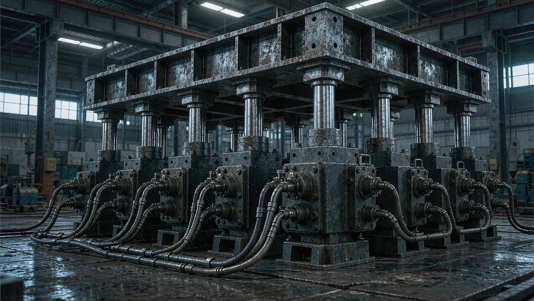
First things first: why is synchronization accuracy so hard to hold?
Synchronization means several actuators holding the same displacement, or the same speed. The ideal is easy to state; reality has a crowd of troublemakers:
- Uneven load — each cylinder carries a different force, so the speeds naturally drift apart.
- Different friction — guides and seals do not resist equally from one cylinder to the next.
- Unequal internal leakage — the clearance leakage of every cylinder and valve differs.
- Manufacturing tolerance — bore diameter and piston area can never be made perfectly identical.
- Oil temperature — change the viscosity and the flow characteristics of every orifice and valve change with it.
All of these make the error accumulate. A good synchronizing circuit therefore has not only to divide evenly, but also to correct.
Mechanical synchronization: locked together by physics
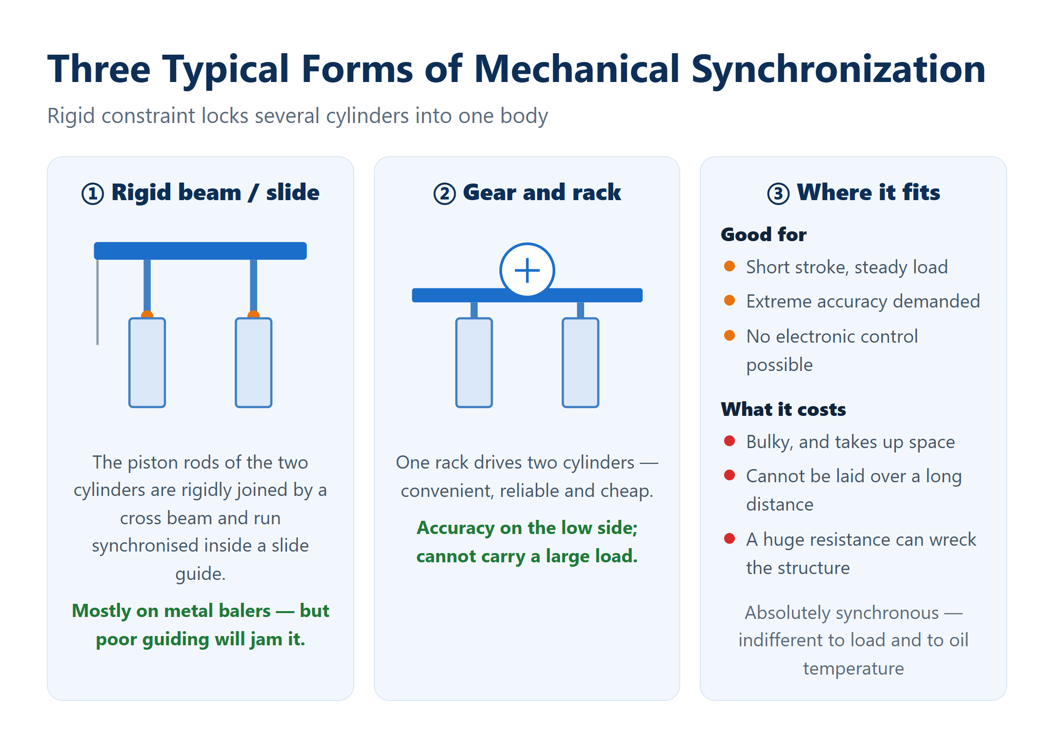
The plainest and most reliable approach is to tie several piston rods physically into one body with a rigid beam, a rack-and-pinion or a slideway. Where the mechanical constraint sits, the displacements are equal — absolutely synchronous, indifferent to load and to oil temperature.
- Rigid beam / slideway connection — features: simple and reliable; mostly used where the load is large, such as metal balers. Condition: the connecting member must have enough rigidity and guide length, otherwise it jams.
- Rack-and-pinion connection — features: one rack drives two cylinders; convenient, reliable and cheap. Limitation: accuracy on the low side, and it cannot take a heavy load.
Where it fits — good for a short stroke, a steady load, extreme accuracy demanded and no electronic control possible. What it costs: a bulky structure, a large footprint, and it cannot be run over a long distance.
Mechanical synchronization wins on stability, but if one cylinder runs into a huge resistance the rigid structure can be destroyed outright. It is not a master key.
The three valve-controlled brothers: throttle, speed-control and divider-combiner
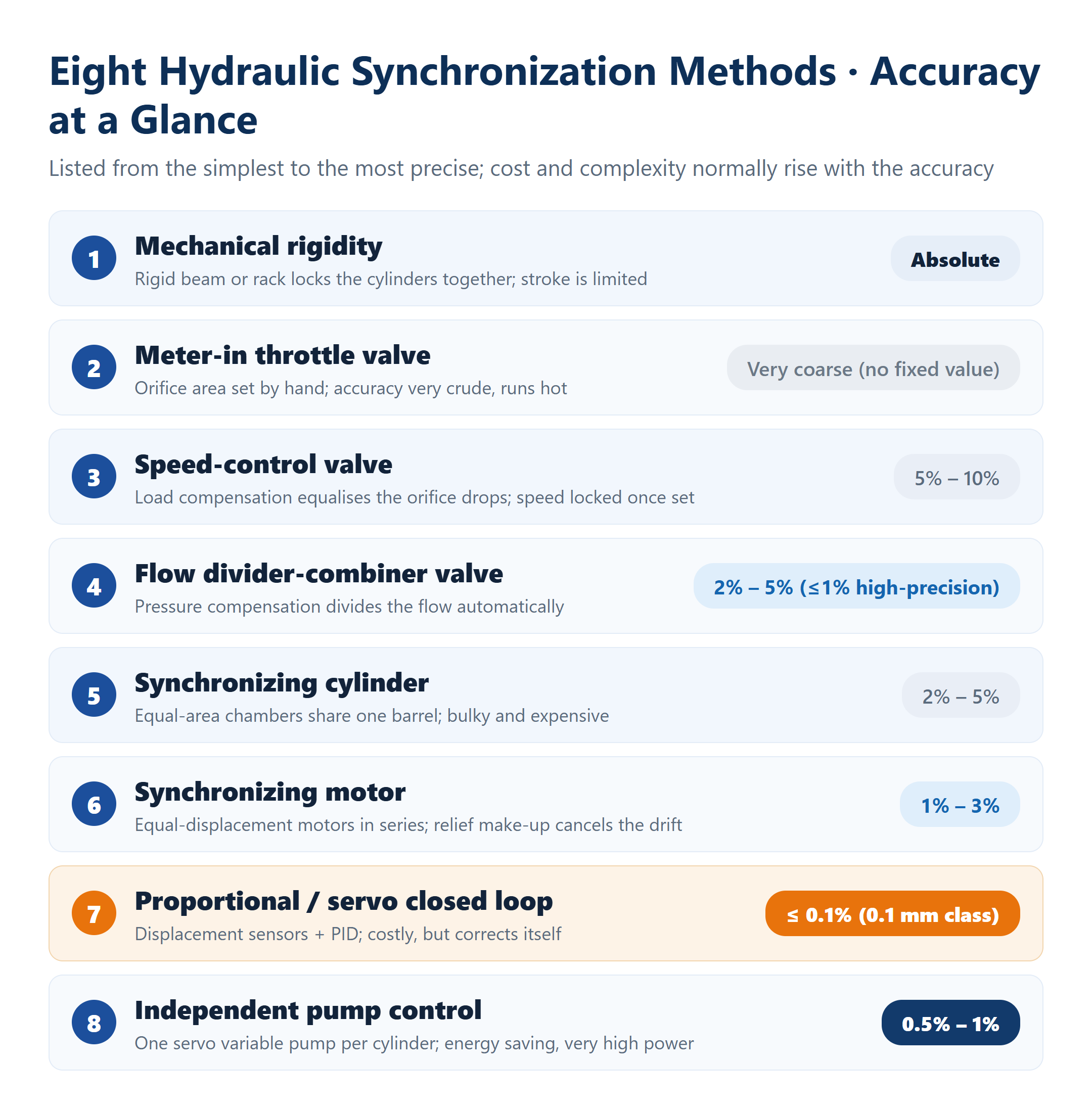
Matching the cylinders by regulating flow is the most common family of schemes in engineering practice, and the three brothers improve in accuracy one after another:
- Meter-in throttle valve: the simplest and crudest — the orifice area is set by hand, accuracy is very limited and it heats badly. Barely usable.
- Speed-control valve: load compensation keeps the pressure drop across both orifices equal, lifting accuracy to 5%–10%; but it is still open loop, and once the speed is set it is locked — no dynamic speed change.
- Flow divider-combiner valve: the metering orifices are integrated into one spool and pressure compensation divides the flow automatically — the most widely applied synchronizing scheme.
The beauty of the divider-combiner valve is that it corrects by itself: even with the two cylinders unevenly loaded the spool moves to compensate and always splits the oil 1:1 — and it does so on the inlet and on the return, giving synchronization in both directions. A standard valve holds 2%–5%; a high-precision servo-adjusted version reaches 1.5%, or even better than 1%.
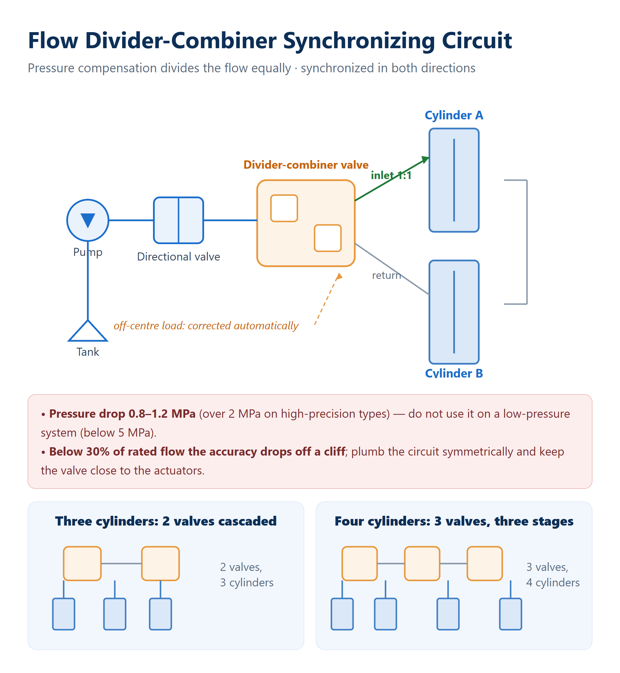
Three traps to remember: ① the valve itself costs a lot of pressure drop (0.8–1.2 MPa, and over 2 MPa on high-precision types), so do not use it on a low-pressure system (below 5 MPa); ② below 30% of rated flow the accuracy falls off a cliff, so choose the nominal flow close to the actual demand; ③ plumb symmetrically and keep the valve as close to the actuators as possible.
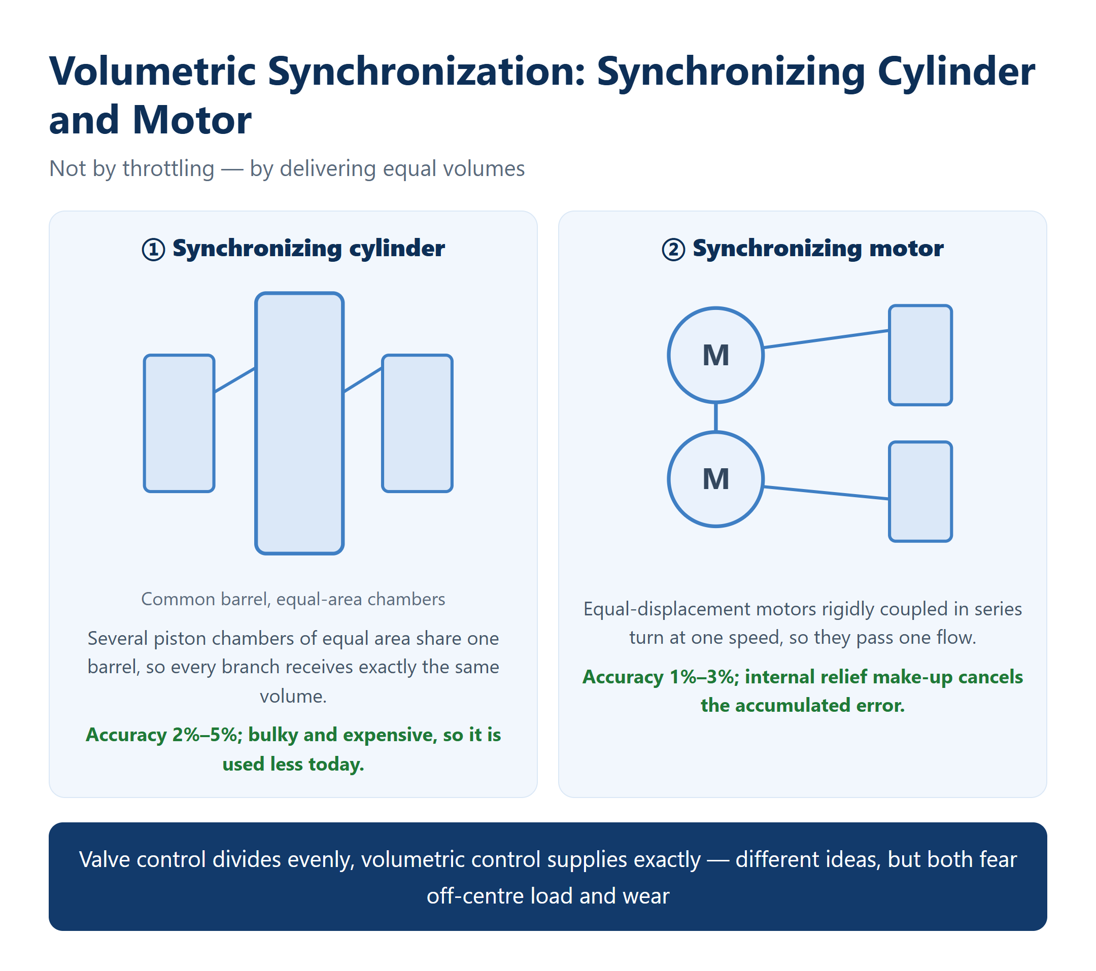
Volumetric synchronization: the synchronizing cylinder and motor
Instead of throttling, this family holds synchronization by equal volumes: every branch gives out the same amount of oil.
- Synchronizing cylinder — principle: one special cylinder with several piston chambers of equal area; the shared barrel guarantees that every branch receives the same flow. Accuracy 2%–5%, usually with a check valve plus a back-pressure valve to drain oil and cancel the error. Big and expensive, so it is used less today.
- Synchronizing motor — principle: several equal-displacement hydraulic motors rigidly coupled in series; identical speed means identical flow. Accuracy 1%–3%, with internal relief and make-up oil removing the accumulated error. Its oil-cleanliness requirement is lower than that of a servo system.
In one line: valve control divides evenly, volumetric control supplies exactly — different ideas, but both fear off-centre load and both fear wear.
Proportional servo closed loop: accuracy down to 0.1%
To attack 0.1%, or even 0.1 mm class accuracy, only a closed loop will do. Every cylinder (or every pair of cylinders) gets a proportional or servo valve, and a displacement sensor on the cylinder reports its position in real time; a PLC or motion controller compares all the sensor signals with a PID algorithm and continuously trims the opening of each valve, flattening the error on the spot.
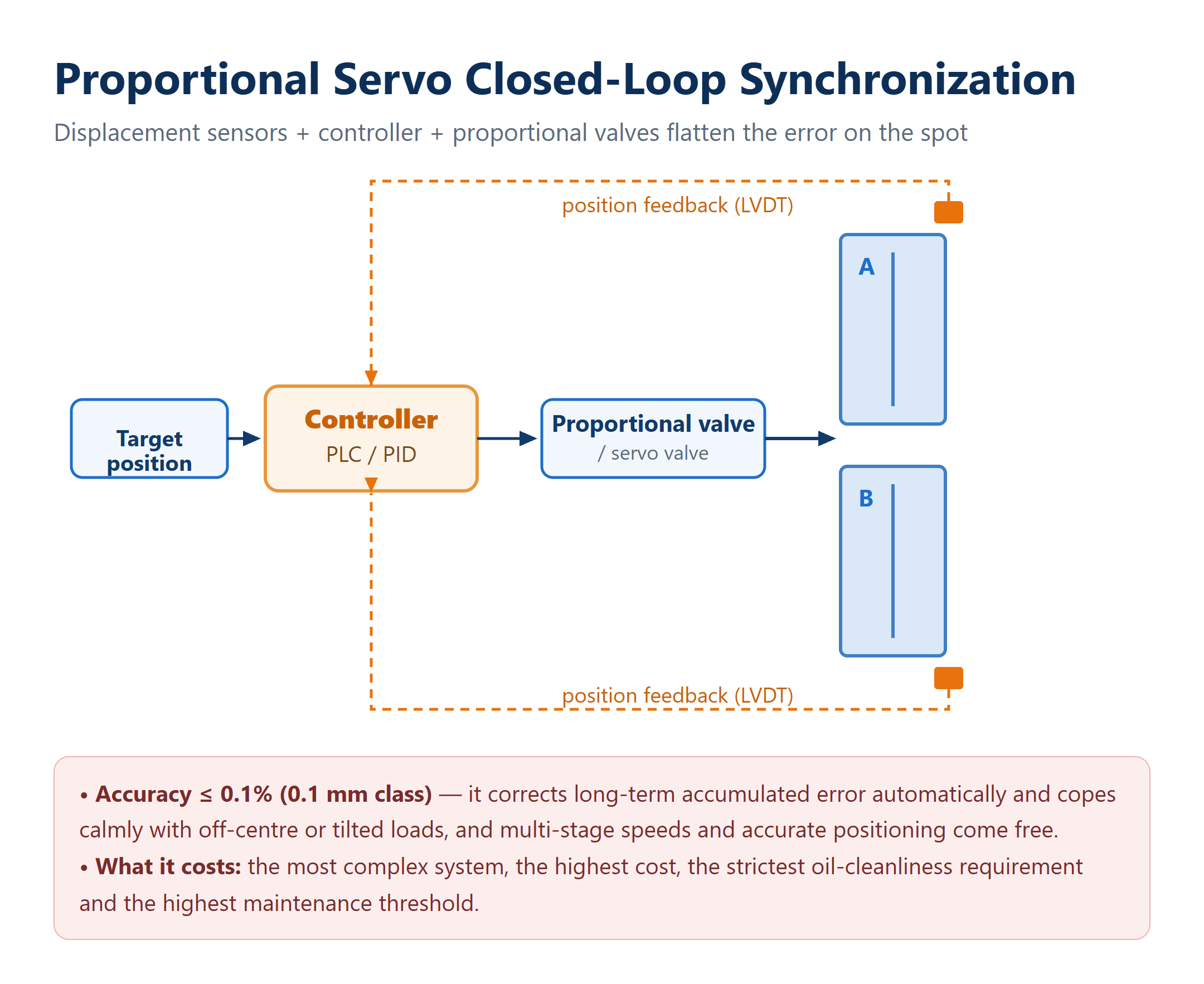
Its greatest strength is that it corrects long-term accumulated error by itself, copes calmly with off-centre and tilted loads, and delivers multi-stage speeds and accurate positioning with ease. The price is the most complex system, the highest cost, the strictest oil-cleanliness requirement and a high maintenance threshold. Choosing it means paying for the top end.
Selection: choosing by accuracy, cost and environment
No method is good or bad, only suitable or not. One decision tree puts you in the right box:
- Low accuracy + harsh environment → divider-combiner valve. Why: cheap and robust; dust and heat do not bother it.
- Medium accuracy + no electronics → synchronizing motor or synchronizing cylinder. Why: more accurate than a divider valve, without an electronic system.
- High accuracy + complex load → proportional servo closed loop. Why: displacement sensors plus a controller give 0.1% class accuracy.
- Very high power / very high dynamic response → independent pump control, one servo variable pump per cylinder. Why: energy saving, no throttling loss, and a fault in one circuit does not drag the others down.

Design pitfalls: the four places a synchronizing circuit goes wrong
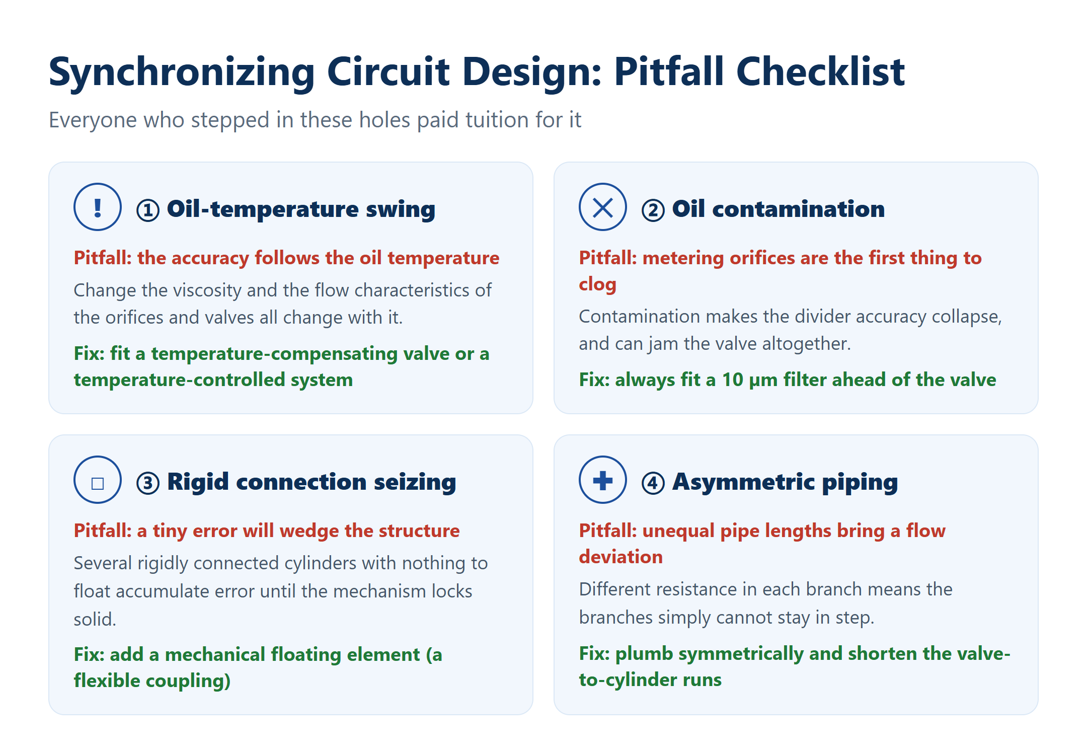
A finished circuit diagram is not a working circuit. Everyone who stepped in these holes paid tuition for it:
- Oil-temperature swing: accuracy follows the oil temperature; fit a temperature-compensating valve or a temperature-controlled system when necessary.
- Oil contamination: the metering orifices of a divider valve are the first thing particles clog; always fit a 10 µm filter ahead of the valve.
- Rigid connections seizing: a rigidly connected multi-cylinder arrangement must have a mechanical floating element (a flexible coupling, for example), otherwise a tiny error wedges it solid.
- Asymmetric piping: unequal pipe lengths bring a flow deviation; plumb as symmetrically as possible and shorten the valve-to-cylinder runs.
发表回复